|
|
|
Porsche, and the Porsche crest are registered trademarks of Dr. Ing. h.c. F. Porsche AG.
This site is not affiliated with Porsche in any way. Its only purpose is to provide an online forum for car enthusiasts. All other trademarks are property of their respective owners. |
|
|

  |

| Prospectfarms |
 Feb 25 2012, 10:43 AM Feb 25 2012, 10:43 AM
Post
#41
|
|
Member  Group: Members Posts: 495 Joined: 7-March 11 From: Louisville, KY Member No.: 12,801 Region Association: Upper MidWest |
QUOTE(mikea100 @ Jan 9 2012, 09:28 PM)  Yesterday, with some help from my 2 boys, I got my '76 2.0 short block on the engine run stand. I need help setting it up. It's late 2.0, complete, all stock, EFI. I'm looking for any info, any help at all. I've read few dozen threads about engine stands, but most of them deal with yokes, adapters and such. I need help with wiring and actually test running the engine. If local guys can stop by this long weekend and land me a hand, you'd really do me a solid and I'll return the favor. I'll serve beer of your choice. (IMG:style_emoticons/default/beerchug.gif) Thanks, Mike Loved the photos of the boys helping and chuckled when I saw your run-stand. Looks like something I would build. Looking forward to see whether your mission is accomplished. Thanks to the various posters for other information. |
   |

 
|
| Tom |
Feb 25 2012, 10:57 AM
Post
#42
|
|
Advanced Member Group: Members Posts: 2,139 Joined: 21-August 05 From: Port Orchard, WA 98367 Member No.: 4,626 Region Association: None |
Did you hook up your relay board? That is needed to tell the fuel pump when to turn on and the ECU power comes from the relay board.
If possible, give us a simple drawing of what you have now and we can get you in the right direction. Common problem when testing like this is too small of a ground wire to battery. Need something large! If you have a good set of jumper cables, use one of them from batt negative to trans case. Tom |
|
|
|
| mikea100 |
Feb 25 2012, 07:08 PM
Post
#43
|
|
Member Group: Members Posts: 180 Joined: 28-December 09 From: Edison, NJ Member No.: 11,182 Region Association: North East States |
Tom,
The relay board is hooked up, however, I have fuel pump and coil hotwired. I have a simple dashboard w/ 3 switches: 1 - push button controls starter, 2 and 3 - toggle switches control coil and fuel pump respectively. FI harness all hooked up - all injectors, MPS, TPS, temp sensors, cold start valve etc. Alternator is connected to the relay board as well. Ignition harness is partially connected, but I don't really need it as I can control starter and coil w/o it. I'm attaching a basic diagram of the setup. It actually works and I can control starter, coil and fuel pump. I'm having difficulties with getting spark in cyl 1. Coil has good spark, but 1 cyl is very weak spark. Once I figured out that spark is the problem I stopped turning on the fuel pump and only use starting fluid in throttle body. Thank you, Mike QUOTE(Tom @ Feb 25 2012, 11:57 AM) Did you hook up your relay board? That is needed to tell the fuel pump when to turn on and the ECU power comes from the relay board. If possible, give us a simple drawing of what you have now and we can get you in the right direction. Common problem when testing like this is too small of a ground wire to battery. Need something large! If you have a good set of jumper cables, use one of them from batt negative to trans case. Tom Attached thumbnail(s) 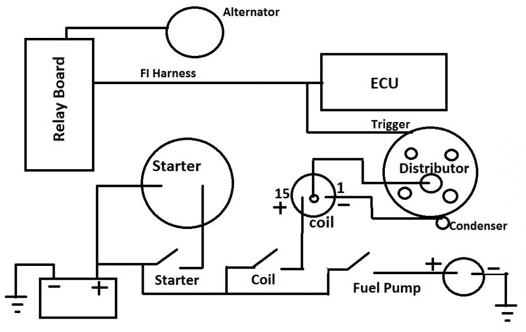
|
|
|
|
| Tom |
Feb 26 2012, 07:46 AM
Post
#44
|
|
Advanced Member Group: Members Posts: 2,139 Joined: 21-August 05 From: Port Orchard, WA 98367 Member No.: 4,626 Region Association: None |
It looks like you are not getting power to the ECU. If you are getting spark, there is no reason why it shouldn't at least fire on some of the cylinders.
It looks like you have the fuel injestion harness hooked up, but are not switching power thru the relay board which is where the ECU is powered from. I think that would be pin 1 of the 4 pin connector You need to provide power to pins 12 and 14, then switched power to 8 and a ground to 10, all on the 14 pin connector. I think that would get power to the ECU. Tom |
|
|
|
| Prospectfarms |
Feb 26 2012, 09:37 AM
Post
#45
|
|
Member Group: Members Posts: 495 Joined: 7-March 11 From: Louisville, KY Member No.: 12,801 Region Association: Upper MidWest |
QUOTE(Tom @ Feb 26 2012, 08:46 AM) It looks like you are not getting power to the ECU. If you are getting spark, there is no reason why it shouldn't at least fire on some of the cylinders. It looks like you have the fuel injestion harness hooked up, but are not switching power thru the relay board which is where the ECU is powered from. I think that would be pin 1 of the 4 pin connector You need to provide power to pins 12 and 14, then switched power to 8 and a ground to 10, all on the 14 pin connector. I think that would get power to the ECU. Tom I hope you don't mind my adding some diagrams, but if I ever build my own run-stand one day, this thread would be a handy reference for the electrical hook-up. Relay board diagrams (courtesy: Jeff Bowlsby) 4pin connector on relay board: (IMG:http://www.914world.com/bbs2/uploads_offsite/bowlsby.net-12801-1330270633.1.jpg) regulator board terminal functions: (IMG:http://www.914world.com/bbs2/uploads_offsite/bowlsby.net-12801-1330270633.2.jpg) Regulator board diagram: (IMG:http://www.914world.com/bbs2/uploads_offsite/bowlsby.net-12801-1330270633.3.jpg) 14 pin connector diagram: (IMG:http://www.914world.com/bbs2/uploads_offsite/bowlsby.net-12801-1330270633.4.jpg) |
|
|
|
| Tom |
Feb 26 2012, 10:09 AM
Post
#46
|
|
Advanced Member Group: Members Posts: 2,139 Joined: 21-August 05 From: Port Orchard, WA 98367 Member No.: 4,626 Region Association: None |
Wow Stuart,
Those are great diagrams. Thanks Jeff! I have to figure out how to save them so I can get to them easily! Tom |
|
|
|
| mikea100 |
Feb 27 2012, 08:05 PM
Post
#47
|
|
Member Group: Members Posts: 180 Joined: 28-December 09 From: Edison, NJ Member No.: 11,182 Region Association: North East States |
Thank you guys, those diagrams are great. My alternator and its harness along w/ relay board are definitely suspects that's why I hotwired fuel pump. I was hoping to completely bypass alternator. But even if ECU doesn't get power it still doesn't explain why there's no spark. My next step is to check and adjust the points. Also, correct me if I'm wrong, but it sounds like if pins 12 and 14 get power, pin 10 gets -grnd - that will completly bypass relay board.
|
|
|
|
| Tom |
Feb 27 2012, 08:54 PM
Post
#48
|
|
Advanced Member Group: Members Posts: 2,139 Joined: 21-August 05 From: Port Orchard, WA 98367 Member No.: 4,626 Region Association: None |
mikea100,
Pins 12 and 14 are the power to the relay board, pin 10 is ground. When you jump power to pin 8, this operates the power relay and provides power to the fuel pump relay and ECU. When the ECU gives a ground to the fuel pump relay, it is energized, giving power to the fuel pump and AAR ( aux air regulator). Here is a pic/dia of the relay board that may help. Tom Attached image(s) 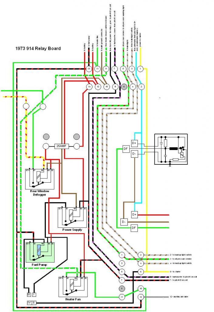
|
|
|
|
|
1 User(s) are reading this topic (1 Guests and 0 Anonymous Users)
0 Members:

|
Lo-Fi Version | Time is now: 20th May 2024 - 04:27 AM |
Invision Power Board
v9.1.4 © 2024 IPS, Inc.